This page illustrates all commands and options available for RapidCompact CLI.
Commands are executed as pipeline, starting with the first, leftmost command and then
continuing with execution of subsequent commands.
In case you want to load and work with multiple 3D assets on the command line, it
is important to know about the asset stack implemented in RapidCompact CLI. In fact,
by using the -i command, a 3D asset is loaded and pushed to this stack,
becoming the stack's top element. If you load a second 3D asset (using
-i again), that one will become the new top element of the stack.
Subsequent operations will then be applied on this asset, unless it is removed again,
using the --pop command. Some commands also need two 3D assets on the
stack to operate, such as --bake (short: -b), which bakes texture maps and
attaches them to one asset (top of the stack), using data from another one (second
highest element on stack).
Another two basic commands are --export (short: -e),
exporting the topmost asset of the stack to a file, and --print_info
(short: -p), printing some basic information about the topmost asset of
the stack to the standard output.
Some important commands are covered in-depth by respective tutorials.
However, to quickly explore all the available commands of RapidCompact CLI and learn about their functionality,
you can simply scroll down this page. Alternatively, you can also directly jump to
the features you are interested in by using the following quick links:
Commands Overview
back to top
Commands: General
| Command (Short) |
#Args |
Example |
Quick Description |
| help (h) |
0 |
-h |
lists all available parameters |
| import (i) |
1 |
-i foo.obj [...] |
imports an asset from a file more |
| export (e) |
1 |
-i foo.obj [...] -e opt.gltf |
exports an asset to a file more |
| export_web (w) |
1 |
-i foo.obj [...] -e viewer |
exports to a directory with HTML 3D viewer more |
| print_info (p) |
0 |
-i foo.obj -p |
prints information about the current 3D asset |
| pop |
0 |
-i foo.obj [...] --pop [...] |
removes the current 3D asset from the stack |
| duplicate |
0 |
-i foo.obj --duplicate [...] |
duplicates the current 3D asset on the stack |
| get (g) |
1 |
-g ao:enabled [...] |
gets the value of the given setting and prints it |
| set (s) |
2 |
-s ao:enabled true [...] |
sets the setting with the given name to the given value |
| read_config |
1 |
--read_config decimation_cfg.json [...] |
reads and apply the given config file more |
| write_config |
1 |
--write_config rpd_config.json |
writes current settings to the given config file more |
Commands: Master Operations
| Command (Short) |
#Args |
Example |
Quick Description |
| compact (c) |
0 |
-i foo.obj -c -e opt.gltf |
turns the current asset into a simplified, textured representation more |
| unwrap (u) |
0 |
-i foo.obj -u -e uvs.obj |
segments and unwraps the current asset, creating a UV atlas more |
Commands: Color and Map Generation
| Command (Short) |
#Args |
Example |
Quick Description |
| colorize_vertex_ao |
0 |
-i foo.obj --colorize_vertex_ao [...] |
computes per-vertex ambient occlusion more |
| set_checker_texture |
0 |
-i foo.obj --set_checker_texture[...] |
assigns a checkerboard texture to the current asset |
| bake_maps (b) |
0 |
-i foo.obj -i bar.obj -b -e uvs.obj |
bakes maps for the current asset, using data from the previous one more |
Commands: Mesh Manipulation
| Command (Short) |
#Args |
Example |
Quick Description |
| decimate (d) |
1 |
-i foo.obj -d v:8000 [...] |
decimates 3D geometry to given no./percentage of vertices/faces more |
| remove_duplicate_vertices |
0 |
-i foo.obj --remove_duplicate_vertices [...] |
removes duplicated vertices from the asset |
Commands: Rendering
| Command (Short) |
#Args |
Example |
Quick Description |
| set_view_matrix (v) |
1 |
-i foo.obj -v "1 0 0 0 0 1 0 0 0 0 1 -23" [...] |
uses a given 3x4 view matrix (instead of computing one) more |
| render_image |
1 |
-i foo.obj --render_image [...] |
renders an image of the current asset to a file more |
| render_turntable |
2 |
-i foo.obj --render_turntable img 32 [...] |
renders a turntable-like image series to a directory more |
Importing and Exporting Meshes
back
to top
To import an asset into the application, use the command --import
(short: -i). The currently supported formats for import are:
- glTF (.gltf and .glb)
- OBJ
- PLY
- STL
- CTM
- STP
- IGES
Exporting a mesh to a file can be achieved using the command --export
(short: -e). The currently supported formats for export are:
- glTF (.gltf and .glb)
- OBJ
- PLY
- STL
- CTM
- USD (.usd and .usdz)
In addition, you can directly export an asset to a 3D HTML viewer, which is ready
for publication on the Web, using the --export_web command (short:
-w). While the --export command receives a filename as
parameter, the --export_web command expects a directory name (will be
created if not existing).
| Texture |
Single Value |
Map Input |
example |
| basecolor |
Kd |
map_Kd |
map_kd material0_albedo.jpg |
| normal |
/ |
norm |
norm material0_normal.png |
| occlusion |
/ |
occlusion |
occlusion material0_occlusion.jpg |
| metallic |
Pm |
map_Pm |
map_Pm material0_metallic.jpg |
| roughness |
Pr |
map_Pr |
map_Pr material0_roughness.jpg |
| emission |
Ke |
map_Ke |
map_Ke material0_emission.jpg |
For proper OBJ import please use the common mtl syntax listed above.
It is noteworthy here that the glTF format uses occlusion, metallic and roughness combined in one RMA texture. RapidCompact is able to read and write those for other formats as well if the maps are assigned correctly.
Simplifying and Texturing 3D Models
back to top
Generating a Compact, Textured Representation
back to top
Generating a compact, textured 3D asset from a high-resolution input mesh is a
complex task. Luckily, RapidCompact CLI has a single master operation for this
purpose. The ratio behind this concept is to make this task as easy as possible,
using a set of well-established default values (which can be altered using settings
API).
Turning a high-resolution input mesh into a compact 3D asset, preserving
the original appearance. Left: Original mesh, consisting of 551,260 triangles.
Right: Compact version with 25,000 triangles, which is less than 5% of
the original geometry. The decimation of less complex input data such as meshes from 3D scans can result in 0,1% and less of the original mesh size.
| Master Operation: |
compact (c) |
| Example: |
rpdx -i myMesh.ply -c -w
outWeb |
| Description: |
Creates a geometrically decimated, textured
representation from a high-resolution mesh. The input mesh may have color or
texture information associated, which will be conserved as good as possible
in the result, using texture maps. To preserve surface details, a normal map
is created. Optionally (via ao settings), ambient occlusion may
be computed when no original color information is available. |
When using
compact, the input mesh is first simplified. Then,
properties of the original mesh are preserved in texture maps, which are applied onto
the low-resolution mesh. Creating texture maps this way is sometimes referred to as
baking. There are several settings which can be used to configure the
parameters of the whole process, the most relevant are typically the resolution of
the mesh geometry and the resolution of the resulting texture maps. Setting the
resolution of the resulting maps is straightforward using settings like
baking:baseColorMapResolution and the respective variants of this setting
for the other maps. However, the setting for the decimation parameter, entitled
decimation:defaultTarget, requires some further explanation:
| Setting Name: |
decimation:defaultTarget |
| Setting Type: |
String |
| Valid Values: |
<number>[%], v:<number>[%],
f:<number>[%] |
| Default Value: |
v:10000 |
| Description: |
Specifies the default target parameter used for
mesh decimation. This can be an absolute number, or a percentage, regarding
either the vertices or faces of the mesh. For example, v:5%
decimates the mesh geometry to 5% of the original vertices. The format of
this setting is identical to the argument format of the decimate
command. |
In contrast to regular commands, the commands for master operations start with a
capital letter. Master operations can usually be broken down into several explicit
commands. For example, instead of using compact, a compact,
textured representation can also be obtained using a chain of explicit, regular
commands, as shown in the following example:
rpdx -i myMesh.ply --duplicate -d 10000 -u -b -w outWeb
Decimating a Mesh
back to top
A common task when preparing 3D data for visualization is to decimate a 3D mesh.
This process typically reduces the mesh geometry in order to speed up data
transmission over networks and rendering performance inside an interactive 3D
application. With RapidCompact CLI, this can be easily done using the decimate
command:
Decimation of an input mesh to 1% of its original vertices, using different
methods. From left to right: Original mesh, result using edge-length based
decimation, result using Quadric-based decimation.
| Command: |
decimate (d) |
| Argument: |
decimation target (number or percentage of
vertices or faces) |
| Example: |
rpdx -i myMesh.ply -d v:1% -e
result.ply |
| Description: |
Decimates a mesh until a given target criterion
is reached. This can be an absolute number, or a percentage, regarding either
the vertices or faces of the mesh. With prefix v:, the number /
percentage of vertices is used as criterion, while prefix f:
specifies that the following is a number / percentage of faces. If no prefix
is given, the argument is interpreted with respect to vertices. The above
example decimates the mesh to 1% of its original vertices. |
The value of the following setting influences the result of the
decimate command:
| Setting Name: |
decimation:method |
| Setting Type: |
String |
| Valid Values: |
quadric, edgeLength |
| Default Value: |
quadric |
| Description: |
Specifies the method to be used for mesh
decimation. The quadric-based ("quadric") decimation usually gives good
results. The edge-length based decimation is slightly faster, and it is
well-suited if you aim at obtaining a highly homogeneous mesh. |
The following command can be used to remove duplicate vertices from a mesh:
| Command: |
remove_duplicate_vertices |
| Example: |
rpdx -i myMesh.ply
--remove_duplicate_vertices -e result.ply |
| Description: |
Removes duplicate vertices from the mesh.
During this step, geometry is re-created, and all surface attributes, such as
texture or vertex colors, are discarded. |
Generating UV Mappings
back to
top
RapidCompact CLI is a powerful tool for texture mapping, exposing several features of the
RapidCompact Library. The UV mapping process typically involves several steps, and can
mainly be divided into the following three stages:
- Segmentation
- Unwrapping
- Atlas Packing
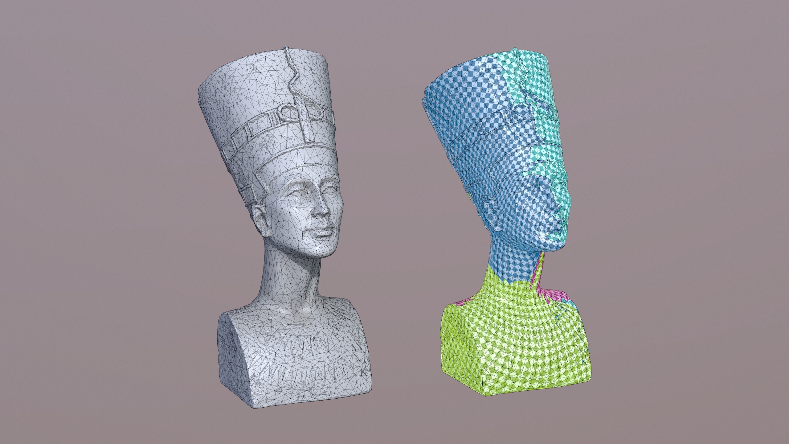
During segmentation, the 3D mesh geometry will be divided into charts that fulfill
certain criteria (such as having disc topology). This step might be necessary, since
not every mesh can be directly unwrapped by all kinds of parameterization algorithms.
Each chart can then be unwrapped separately. During this step, the actual generation
of 2D UV coordinates takes place. Finally, the third step arranges one or multiple
charts in a (usually square) 2D domain, which is called a Texture Atlas.
Segmenting a mesh into optimized charts for texturing.
RapidCompact CLI does not provide explicit commands for atlas packing. Instead, the atlas
packing step is part of the unwrap command. This is motivated by the
fact that an unwrapping of multiple charts without atlas packing, leading to overlaps
inside the UV space, is usually not usable for very most applications, and may lead
to unexpected results in many cases. Within the following, the
unwrapping command and related settings (including such for texture packing) are
illustrated.
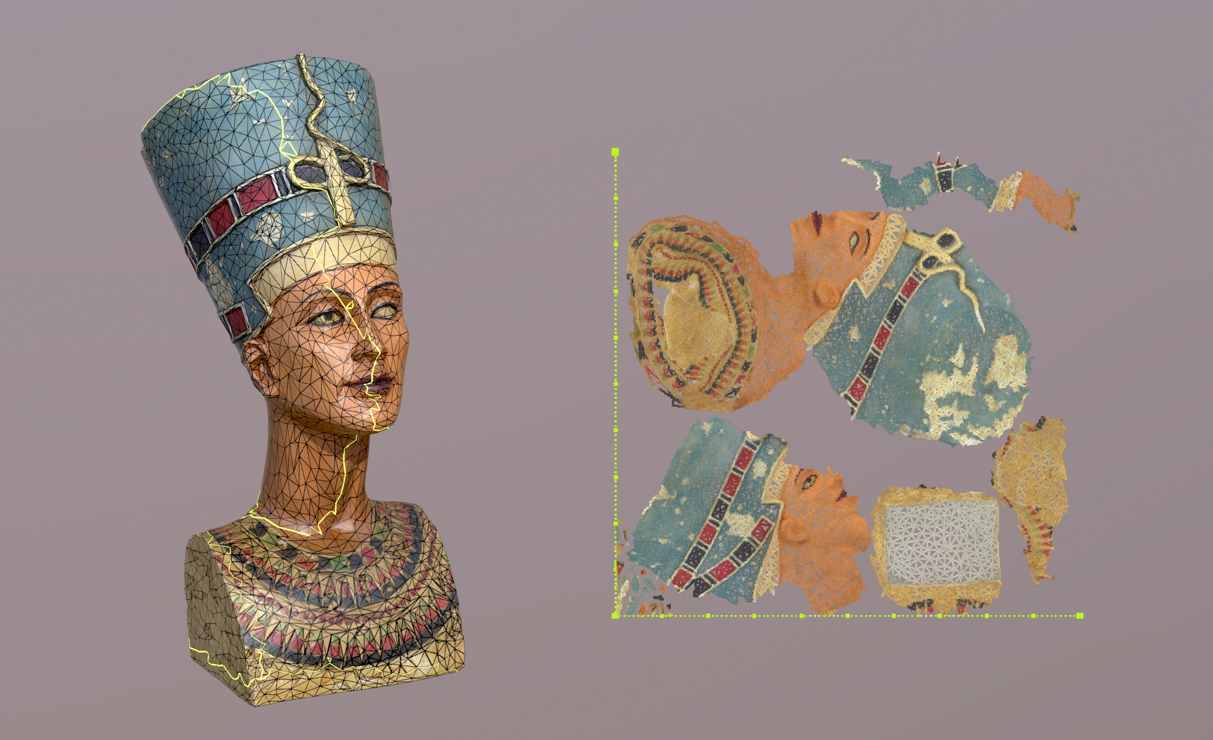
Computing UV coordinates for a 3D mesh is for sure one of the most crucial steps
within a texture mapping pipeline. RapidCompact CLI
offers a fast, high-quality unwrapping which is by default configured preventing
the occurance of any overlaps. The respective command
(--unwrap) is further explained within the following.
Computing UV coordinates for a segmented mesh. Left: segmented 3D mesh. Right:
UV atlas.
| Command: |
unwrap |
| Example: |
rpdx -i myMesh.ply -u -e
myMesh-UV.obj |
| Description: |
Computes a UV mapping for a segmented mesh (or
for a single mesh with disc topology). Charts are first unwrapped and then
packed into a texture atlas. |
The values of the following settings influence the result of the unwrap command:
| Setting Name: |
unwrapping:method |
| Setting Type: |
String |
| Valid Values: |
conformal, fastConformal, isometric, forwardBijective,
fixedBoundary |
| Default Value: |
fastConformal |
| Description: |
Specifies the method to be used for UV unwrapping. The different methods
are:
- conformal:
A very fast method, producing results of good quality. This method tries
to avoid stretch by minimizing the error in angles. It may produce
self-overlaps, so make sure to enable
unwrapping:cutOverlappingPieces if you want overlap-free
UVs.
- fastConformal:
Sightly faster than conformal, producing a good approximation of the conformal
method. It may also produce self-overlaps, so make sure to enable
unwrapping:cutOverlappingPieces if you want overlap-free
UVs.
- isometric:
A balanced method, producing results of best possible quality. This
method tries to avoid stretch by minimizing the error in angles and
areas. It may produce self-overlaps, so make sure to enable
unwrapping:cutOverlappingPieces if you want overlap-free
UVs.
- forwardBijective:
A sophisticated method, producing results of high possible quality that
are guaranteed to have no overlaps. This method tries to avoid stretch by
minimizing the error in angles and areas. Since it never produces
self-overlaps, a separate cutting step is not necessary.
- fixedBoundary:
A fast, very basic method, pinning the boundary of the UVs to a circle
and then computing interior UV coordinates. Results are guaranteed to
have no self-overlaps. Due to the circular shape, results will only have
low stretch if the 3D shape has an approximately circular boundary.
|
| Setting Name: |
packing:chartPadding |
| Setting Type: |
Real |
| Valid Range: |
[0, 1) |
| Default Value: |
~0.0005 (1.0/2048) |
| Description: |
Specifies the amount of padding to be used
around each chart within the UV atlas. The value is interpreted relative to
the unit range of the atlas. This means that, for example, a value of 1/1000
will produce a padding of one thousandth of the atlas' size around each
chart. If the constraint cannot be fulfilled (for example, because there are
too many charts), it will be relaxed accordingly. |
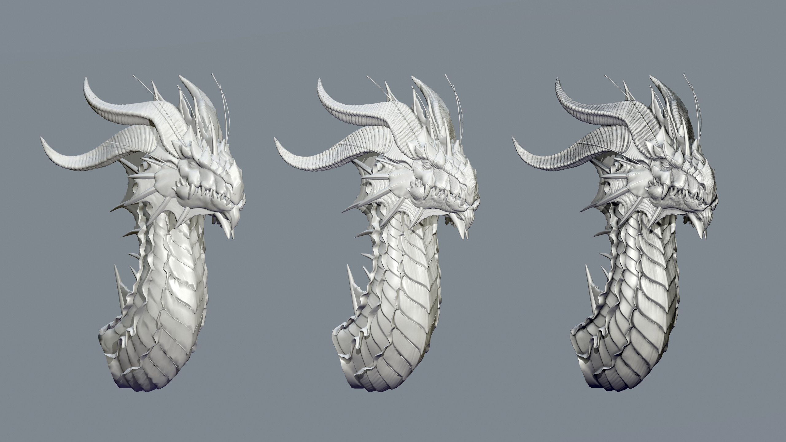
Generating Color Information and Textures
back to top
The following commands can be used to create vertex colors or texture maps:
Storing computed AO (Ambient Occlusion) values in vertex colors or as a texture. Left: Compact model
without vertex colors and textures. Center: Asset with automatically baked normal map. Right: Asset with AO.
| Command: |
colorize_vertex_ao |
| Example: |
rpdx -i myMesh.ply --colorize_vertex_ao
-e myMesh-ao.ply |
| Description: |
Computes computed AO (Ambient Occlusion) at
each vertex and colors the vertices accordingly. |
The following setting influences the result and running time of the ambient
occlusion computation:
| Setting Name: |
ao:vertexSamples |
| Setting Type: |
Integer Number |
| Valid Range: |
[1, 1024] |
| Default Value: |
100 |
| Description: |
Specifies the number of samples taken for each
vertex when generating ambient occlusion values. Larger values result in more
precise occlusion computation, at the cost of longer computation times. |
| Command: |
set_checker_texture |
| Example: |
rpdx -i mesh-UVs.obj
--set_checker_texture -e mesh-checker.obj |
| Description: |
Attaches a checkerboard texture to the 3D
asset. This is primarily useful to visualize the properties (stretch, scale
and direction) of a UV mapping. |
The following bake_maps command can be used to create texture maps
for a low-resolution mesh, in order to visualize it with detailed surface properties
from a corresponding high-resolution variant (such as normals, stored in a normal
map). The process of creating such textures is also referred to as
baking.
Normal map (object-space) and Albedo map (base color) for a textured low-resolution mesh, generated from the
corresponding high-resolution original. For illustration purposes, this
texture atlas was generated without inpainting.
| Command: |
bake_maps |
| Example: |
rpdx -i highpoly.obj -i lowpoly-UV.obj
-b -w outWeb |
| Description: |
Transfers attributes of a source asset into
texture maps of destination mesh, using the UV mapping of the destination
asset. The second highest asset of the stack acts as source asset, the
topmost asset of the stack acts as destination asset. Usually, a normal map
and a base color / albedo map are created. If the destination asset does not
have color information (such as vertex colors or textures), it is possible to
create the base color / albedo texture using ambient occlusion, computed on
the source asset. |
Apart from the baking:baseColorMapResolution setting and similar settings
for resolutions of the other maps, the following settings influence the result of the
bake_maps command:
| Setting Name: |
inpainting:radius |
| Setting Type: |
Integer |
| Valid Values: |
[0, 32] |
| Default Value: |
32 |
| Description: |
Specifies the radius, in pixels, to be used for
texture inpainting around each chart. |
| Setting Name: |
ao:enabled |
| Setting Type: |
Flag |
| Valid Values: |
true, false |
| Default Value: |
false |
| Description: |
Specifies if generation of AO texture maps is
enabled. |
| Setting Name: |
ao:replaceMissingAlbedo |
| Setting Type: |
Flag |
| Valid Values: |
true, false |
| Default Value: |
true |
| Description: |
Specifies if AO should be used to replace a
missing albedo / base color texture, in case no such texture is available on
the source asset during baking. If this flag is switched off, AO will always
be written to a separate, dedicated texture map. |
| Setting Name: |
ao:textureSamples |
| Setting Type: |
Integer Number |
| Valid Range: |
[1, 64] |
| Default Value: |
8 |
| Description: |
Specifies the number of samples taken for each
texel when generating an ambient occlusion texture. Larger values result in
more precise occlusion computation, at the cost of longer computation
times. |
| Setting Name: |
ao:filterRadius |
| Setting Type: |
Real |
| Valid Range: |
[0, 16] |
| Default Value: |
5.0 |
| Description: |
Specifies the filter radius used for smoothing
the ambient occlusion texture (if any). Set the filter radius to 0 to disable
smoothing. |
Generating Images
back to top
Since it can easily be installed on servers an does not require a GPU, RapidCompact CLI
can also be conveniently used to generate images of 3D models. This is useful, for
example, when you have a large set of meshes and want to create thumbnail images. You
can also use RC to render a turntable-like image series, rotating around the
up-axis of a given mesh. Such an image series can then be used to display a pseudo-3D
view of a 3D model (for example, inside a Web page). Image generation (or
rendering) commands share the following common settings:
| Setting Name: |
rendering:imageWidth (similar:
rendering:imageHeight) |
| Setting Type: |
Integer Number |
| Valid Range: |
[1, 8192] |
| Default Value: |
1024 |
| Description: |
Specifies the width (similar: height) for
rendered images. |
| Setting Name: |
rendering:background |
| Setting Type: |
String |
| Valid Values: |
transparent, white, black, gradientGray |
| Default Value: |
transparent |
| Description: |
Specifies the background to be used when
rendering images. |
| Setting Name: |
rendering:showBackFaces |
| Setting Type: |
Flag |
| Valid Values: |
true, false |
| Default Value: |
false |
| Description: |
Specifies whether faces with a surface normal
pointing away from the viewer ("backfaces") should be rendered. |
If a model should be rendered using a certain camera position and orientation, the
following command set_view_matrix can be used:
| Command: |
set_view_matrix |
| Shorthand: |
v |
| Argument: |
matrix in format "m00 m01 m02 m03 m10 m11 m12
m13 m20 m21 m22 m23" |
| Example: |
rpdx -i foo.obj -v "1 0 0 0 0 1 0 0 0 0 1
-1000" --render_image foo.png |
| Description: |
Sets the view matrix, used for rendering, to
the given matrix. The 3x4 matrix in row major format must be specified as a
single, whitespace-separated string, wrapped in quotes. |
If no view matrix is explicitly set, the model is rendered with the camera fitting
to the scene, looking along the negative z-axis (if the system was not rotated). The
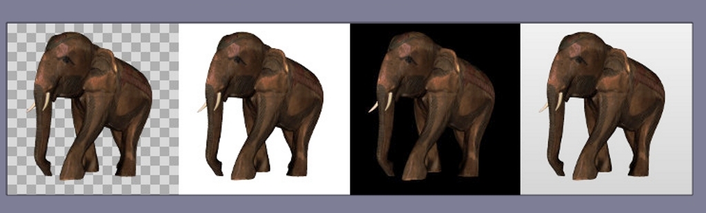
commands for generating images are shown in the following.
Images generated with different backgrounds. Background names from left to
right: "transparent", "white", "black", "gradientGray".
| Command: |
render_image |
| Shorthand: |
none |
| Argument: |
filename of the resulting image file |
| Example: |
rpdx -i myMesh.ply --render_image
mesh.png |
| Description: |
Renders an image of a mesh and stores it to the
given image file. Supported image formats are PNG and JPEG. |
| Command: |
render_turntable |
| Argument 1: |
directory for images |
| Argument 2: |
number of views / images to render |
| Example: |
rpdx -i foo.obj --render_turntable meshTT
32 |
| Description: |
Renders a turntable-like image series by
centering the asset and rotating the view around the up-axis. The resulting
images will be stored in PNG format. |