This page illustrates all commands and options available for RapidCompact CLI. Commands are executed as pipeline, starting with the first, leftmost command and then continuing with execution of subsequent commands.
If you are already familiar with the system, you can find a quick overview of all available commands and settings within the command cheat sheet.
A command can be specified using two dashes and the command's name, which is then followed by the command's arguments (if any). Some commands have an additional shorthand version, which is only using a single dash and a single letter (most times the first one) of the command's name. Example:
rpdx -i myMesh.obj -c -w outputWeb
This example imports a 3D asset from a file called "myMesh.obj"(using -i
myMesh.obj as shorthand for --import myMesh.ply). It then
generates a compact, textured representation (using -c as shorthand for --compact).
Finally, RapidCompact CLI writes the result to a Web-ready standalone visualization inside a
(new or existing) directory with name "outputWeb" (using -w outputWeb as
shorthand for --export_web outputWeb)
In case you want to load and work with multiple 3D assets on the command line, it
is important to know about the asset stack implemented in RapidCompact CLI. In fact,
by using the -i command, a 3D asset is loaded and pushed to this stack,
becoming the stack's top element. If you load a second 3D asset (using
-i again), that one will become the new top element of the stack.
Subsequent operations will then be applied on this asset, unless it is removed again,
using the --pop command. Some commands also need two 3D assets on the
stack to operate, such as --bake_maps (short: -b), which bakes texture maps and
attaches them to one asset (top of the stack), using data from another one (second
highest element on stack).
Another two basic commands are --export (short: -e),
exporting the topmost asset of the stack to a file, and --print_info
(short: -p), printing some basic information about the topmost asset of
the stack in the standard output.
To explore the available commands of RapidCompact CLI and learn about their functionality, you can simply scroll down this page. Alternatively, you can also directly jump to the features you are interested in by using the following quick links:
- Commands & Settings Cheat Sheet
- Importing and Exporting Meshes
- Configuration
- Simplifying and Texturing 3D Models
- Generating Color Information and Textures
- Generating Images
RapidCompact CLI 1.6 Commands & Settings Cheat Sheet
back to topCommands: General
| Command (Short) | #Args | Example | Quick Description |
|---|---|---|---|
| help (h) | 0 | -h | lists all available parameters |
| import (i) | 1 | -i foo.obj [...] | imports an asset from a file more |
| export (e) | 1 | -i foo.obj [...] -e opt.gltf | exports an asset to a file more |
| export_web (w) | 1 | -i foo.obj [...] -e viewer | exports to a directory with HTML 3D viewer more |
| print_info (p) | 0 | -i foo.obj -p | prints information about the current 3D asset |
| pop | 0 | -i foo.obj [...] --pop [...] | removes the current 3D asset from the stack |
| duplicate | 0 | -i foo.obj --duplicate [...] | duplicates the current 3D asset on the stack |
| get (g) | 1 | -g ao:enabled [...] | gets the value of the given setting and prints it more |
| set (s) | 2 | -s ao:enabled true [...] | sets the setting with the given name to the given value more |
| read_config | 1 | --read_config decimation_cfg.json [...] | reads and apply the given config file more |
| write_config | 1 | --write_config rpd_config.json | writes current settings to the given config file more |
Commands: Master Operations
| Command (Short) | #Args | Example | Quick Description |
|---|---|---|---|
| compact (c) | 0 | -i foo.obj -c -e opt.gltf | turns the current asset into a simplified, textured representation more |
| unwrap (u) | 0 | -i foo.obj -u -e uvs.obj | segments and unwraps the current asset, creating a UV atlas more |
Commands: Color and Map Generation
| Command (Short) | #Args | Example | Quick Description |
|---|---|---|---|
| colorize_vertex_ao | 0 | -i foo.obj --colorize_vertex_ao [...] | computes per-vertex ambient occlusion more |
| set_checker_texture | 0 | -i foo.obj --set_checker_texture[...] | assigns a checkerboard texture to the current asset |
| bake_maps (b) | 0 | -i foo.obj -i bar.obj -b -e uvs.obj | bakes maps for the current asset, using data from the previous one more |
Commands: Mesh Manipulation
| Command (Short) | #Args | Example | Quick Description |
|---|---|---|---|
| decimate (d) | 1 | -i foo.obj -d v:8000 [...] | decimates 3D geometry to given no./percentage of vertices/faces more |
| remove_duplicate_vertices | 0 | -i foo.obj --remove_duplicate_vertices [...] | removes duplicated vertices from the asset |
Commands: Rendering
| Command (Short) | #Args | Example | Quick Description |
|---|---|---|---|
| set_view_matrix (v) | 1 | -i foo.obj -v "1 0 0 0 0 1 0 0 0 0 1 -23" [...] | uses a given 3x4 view matrix (instead of computing one) more |
| render_image | 1 | -i foo.obj --render_image [...] | renders an image of the current asset to a file more |
| render_turntable | 2 | -i foo.obj --render_turntable img 32 [...] | renders a turntable-like image series to a directory more |
Settings
See this section on how to configure settings.| Name | Type | Default | Valid Range | Quick Description |
|---|---|---|---|---|
| ao:enabled | Flag | false | {true, false} | turns AO (Ambient Occlusion) generation on/off |
| ao:filterRadius | Real | 5 | [0.0, 16.0] | filter radius for smoothing the AO map (if any) |
| ao:replaceMissingAlbedo | Flag | true | {true, false} | turns replacement of missing base color by AO map on/off |
| ao:textureSamples | Integer | 8 | [1, 64] | number of samples per texel for AO map generation |
| ao:vertexSamples | Integer | 100 | [1, 1024] | number of samples per vertex for AO generation |
| baking:baseColorMapResolution | Integer | 2048 | [1, 8192] | resolution for baked base color maps |
| baking:displacementMapResolution | Integer | 2048 | [1, 8192] | resolution for baked displacement maps |
| baking:forcedDisplacementMin | Real | 0.0 | (-inf, inf) | when forcedDisplacementMax and forcedDisplacementMax are given and valid (min < max), their values are used to clamp and normalize the final entries in the displacement map |
| baking:forcedDisplacementMax | Real | 0.0 | (-inf, inf) | (see baking:forcedDisplacementMin) |
| baking:generateDisplacement | Flag | false | {true, false} | enables/disables the generation of displacement maps |
| baking:generateNormal | Flag | true | {true, false} | enables/disables the generation of normal maps |
| baking:normalMapResolution | Integer | 2048 | [1, 8192] | resolution for baked normal maps |
| baking:occlusionMapResolution | Integer | 2048 | [1, 8192] | resolution for baked AO maps |
| baking:sampleCount | Integer | 1 | {1, 4, 8} | number of samples per pixel for texture baking |
| baking:tangentSpaceNormals | Flag | true | {true, false} | switches between tangent-/object-space normal maps |
| decimation:boundaryPreservationFactor | Real | 0.5 | [0, 1] | factor to steer preservation of boundaries during decimation |
| decimation:collapseDistanceThreshold | Real | 0.05 | [0, 0.1] | threshold w.r.t BBox diagonal for collapsing nearby vertices |
| decimation:collapseUnconnectedVertices | Flag | true | {true, false} | switches collapsing of nearby, unconnected vertices on/off |
| decimation:defaultTarget | String | "f:20000" | * | target parameter for decimation during compact |
| decimation:preserveTopology | Flag | false | {true, false} | switches computation of new normals after decimation on or off |
| decimation:recomputeNormals | Flag | true | {true, false} | switches computation of new normals after decimation on or off |
| decimation:method | String | "quadric" | {"quadric", "edgeLength"} |
method to be used for decimation |
| decimation:qualityWeight | Real | 0 | [0, 1] | weights for vertex quality values during decimation, if any |
| export:baseColorMapFormat | String | "jpg" | {"png", "jpg"} | desired output file format for base color maps |
| export:centerModel | Flag | false | {true, false} | centers the model around the coordinate origin before export |
| export:displacementMapFormat | String | "jpg" | {"png", "jpg"} | desired output file format for displacement maps |
| export:displacementToNormalMapAlpha | Flag | false | {true, false} | bakes displacement values into the normal map's alpha channel |
| export:emissiveMapFormat | String | "jpg" | {"png", "jpg"} | desired output file format for emissive maps |
| export:metallicMapFormat | String | "jpg" | {"png", "jpg"} | desired output file format for metallic maps |
| export:roughnessMapFormat | String | "jpg" | {"png", "jpg"} | desired output file format for roughness maps |
| export:normalMapFormat | String | "jpg" | {"png", "jpg"} | desired output file format for normal maps |
| export:occlusionMapFormat | String | "jpg" | {"png", "jpg"} | desired output file format for occlusion maps |
| export:preferBinaryFormat | Flag | true | {true, false} | turns export in binary format on/off (if available) |
| export:textureMapFilePrefix | String | "" | valid strings (ex.: "my-model-023") | prefix to be used for texture map names |
| export:unlitMaterials | Flag | false | {true, false} | enables that all materials are specified as unlit, for .gltf/.glb export |
| general:maxConcurrentThreads | Integer | 0 | [0, inf) | maximum number of concurrent threads. 0 means no limit (adapts to number of cores), other numbers act as fixed maximum. |
| general:normalsHardAngleDeg | Real | 180.0 | [0, 180.0] | hard angle (degrees) used for normal generation (0 = everything flat, 180 = everything smooth) |
| import:rotateZUp | Flag | false | {true, false} | turns rotation to z-axis pointing upwards on/off |
| inpainting:radius | Integer | 32 | [0, 32] | radius, in pixels, for texture inpainting |
| logging:infoLevel | Integer | 3 | [0, 4] | logging verbosity (0 = quiet, 4 = debug) |
| material:defaultBaseColor | String | "1 1 1" | [0, 1]^3 | default material base color |
| material:defaultMetallic | Real | 0.2 | [0,1] | default material metallic property |
| material:defaultRoughness | Integer | 0.4 | [0, 1] | default material roughness property |
| packing:chartPadding | Real | 1.0/2048 | [0, 1) | relative desired padding around charts inside the UV atlas |
| rendering:background | String | "transparent" | {"transparent", "white", "black", "gradientGray"} |
background to be used for rendered images |
| rendering:imageHeight | Integer | 1024 | [1, 8192] | height to be used for rendered images |
| rendering:imageWidth | Integer | 1024 | [1, 8192] | width to be used for rendered images |
| rendering:showBackFaces | Flag | false | {true, false} | turns rendering of backfaces on/off |
| segmentation:chartAngleDeg | Real | 130.0 | [0, 360] | threshold (degrees) for overall curvature of 3D charts |
| segmentation:cutAngleDeg | Real | 88.0 | [0, 180] | threshold (degrees) for cutting sharp edges |
| segmentation:maxPrimitivesPerChart | Integer | 10000 | setting to limit number of primitives per chart | [1,inf) |
| unwrapping:cutOverlappingPieces | Flag | true | {true, false} | turns removal of UV self-overlaps through cutting on/off |
| unwrapping:method | String | "isometric" | {"conformal", "fastConformal", "isometric", "forwardBijective", "fixedBoundary"} |
method to be used for UV unwrapping |
Importing and Exporting Meshes
back to topTo import an asset into the application, use the command --import
(short: -i). The currently supported formats for import are:
- glTF (.gltf and .glb)
- OBJ
- PLY
Exporting a mesh to a file can be achieved using the command --export
(short: -e). The currently supported formats for export are:
- glTF (.gltf and .glb)
- OBJ
- PLY
In addition, you can directly export an asset to a 3D HTML viewer, which is ready
for publication on the Web, using the --export_web command (short:
-w). While the --export command receives a filename as
parameter, the --export_web command expects a directory name (will be
created if not existing).
| Texture | Single Value | Map Input | example |
|---|---|---|---|
| basecolor | Kd | map_Kd | map_kd material0_albedo.jpg |
| normal | / | norm | norm material0_normal.png |
| occlusion | Ka | map_Ka | map_Ka material0_occlusion.jpg |
| metallic | Pm | map_Pm | map_Pm material0_metallic.jpg |
| roughness | Pr | map_Pr | map_Pr material0_roughness.jpg |
For proper OBJ import please use the common mtl syntax listed above. It is noteworthy here that the gltf format uses occlusion, metallic and roughness combined in one RMA texture. RapidCompact is able to read and write those for other formats as well if the maps are assigned correctly.
Configuration
back to topCreating and Using a Config File
back to topSome parameters for RapidCompact CLI are directly available with the respective commands. However, many relevant options (like the choice of a specific algorithm for a certain task) are only available via the Settings mechanism of RapidCompact CLI. The ratio behind this is to ease usage of the command line, especially for users that are not familiar with all the details, while still allowing you to configure all relevant parameters when necessary.
One way to configure the settings is to use a Config File. The config
file is a text file in JSON format, which can be easily edited. To create one that
already contains the default values for all the available settings, use the command
write_config with a filename. Example:
rpdx --write_config rpd_config.json
Additionally it is possible to just use the short command
write_config without an argument. The resulting file will always be named as default: rpd_config.json Example:
rpdx --write_config
This example writes a config file with filename "rpd_config.json". This special
filename is used by RapidCompact CLI to check, on startup, for an existing config file inside
the current directory. If the file has another filename, or if it is placed at
another location, you can use the read_config command to read it when
launching RapidCompact CLI. Example:
rpdx --read_config someDirectory/myConfig.json
Changing the settings inside a config file is pretty straightforward - just use your favorite text editor to alter the default values and save the file. When looking into a config file, you will notice that settings' names are using a URN-like scheme, separating several parts of the name by a colon. Examples:
             [...]
             "decimation:method" : "quadric",
             "rendering:imageWidth"  : 1024,
             "rendering:imageHeight" : 1024,
             [...]
The colons are used to separate different parts of each setting's name, where the first part is always the subsystem of RapidCompact CLI that uses the setting. In the above example, for instance, the prefix "rendering" tells us that the following part "imageWidth" refers to a setting inside that subsystem (and nowhere else). For example, the width of images for texture generation will not be affected by this setting.
Changing Settings using the Command Line
back to topSometimes, you might want to try out different settings without having to use a
config file. This is easily possible by using the command set
(shorthand: s). Example:
rpdx -i myMesh.ply -s decimation:method edgeLength --decimate v:10% -e myMesh-decimated.ply
In this example, a mesh is loaded and its 3D geometry is decimated to 10% of the
original vertices. Instead of using the standard decimation method or the one from
the default config file, the decimation is explicitly set to
"edgeLength" before the decimater is used.
In general, the default value of a setting can be overriden in both ways, using a
config file or using the command line. Both methods, using a config file and using
s on the command line, override the current values of the given
settings, so the current value of a setting also depends on the order in which
previous read_config or s commands are executed. If you
have use for this, you can also split up one large config file into multiple smaller
ones, to separate different aspects of configuration. This is possible since the
settings specified inside the config file do not need to be complete. Instead, a
config file will only override settings for the parameters that are specified,
leaving unspecified settings untouched. Example:
rpdx --read_config decimation_config.json --read_config rendering_config.json ...
Finally, to print the current value of a setting, there is also a get
command (shorthand: g).
Changing Logging Verbosity
back to topBy default, RapidCompact CLI will print some information to the standard output while executing commands. By specifying a log level, you can influence how verbose this output will be. To do so, use the "logging:infoLevel" setting. The corresponding values are:
- 0 - NONE: quiet mode, no logging
- 1 - ERRORS: only errors are shown
- 2 - WARNINGS: only errors and warnings are shown
- 3 - INFOS: errors, warnings and regular info messages are shown
- 4 - DEBUG: verbose mode, all information available is shown
Simplifying and Texturing 3D Models
back to topGenerating a Compact, Textured Representation
back to topGenerating a compact, textured 3D asset from a high-resolution input mesh is a complex task. Luckily, RapidCompact CLI has a single master operation for this purpose. The ratio behind this concept is to make this task as easy as possible, using a set of well-established default values (which can be altered using settings API).
| Master Operation: | compact (c) |
| Example: | rpdx -i myMesh.ply -c -w
outWeb |
| Description: | Creates a geometrically decimated, textured
representation from a high-resolution mesh. The input mesh may have color or
texture information associated, which will be conserved as good as possible
in the result, using texture maps. To preserve surface details, a normal map
is created. Optionally (via ao settings), ambient occlusion may
be computed when no original color information is available. |
compact, the input mesh is first simplified. Then,
properties of the original mesh are preserved in texture maps, which are applied onto
the low-resolution mesh. Creating texture maps this way is sometimes referred to as
baking. There are several settings which can be used to configure the
parameters of the whole process, the most relevant are typically the resolution of
the mesh geometry and the resolution of the resulting texture maps. Setting the
resolution of the resulting maps is straightforward using settings like
baking:baseColorMapResolution and the respective variants of this setting
for the other maps. However, the setting for the decimation parameter, entitled
decimation:defaultTarget, requires some further explanation:
| Setting Name: | decimation:defaultTarget |
| Setting Type: | String |
| Valid Values: | <number>[%], v:<number>[%], f:<number>[%] |
| Default Value: | v:10000 |
| Description: | Specifies the default target parameter used for
mesh decimation. This can be an absolute number, or a percentage, regarding
either the vertices or faces of the mesh. For example, v:5%
decimates the mesh geometry to 5% of the original vertices. The format of
this setting is identical to the argument format of the decimate
command. |
In contrast to regular commands, the commands for master operations start with a
capital letter. Master operations can usually be broken down into several explicit
commands. For example, instead of using compact, a compact,
textured representation can also be obtained using a chain of explicit, regular
commands, as shown in the following example:
rpdx -i myMesh.ply --duplicate -d 10000 -u -b -w outWeb
Decimating a Mesh
back to topA common task when preparing 3D data for visualization is to decimate a 3D mesh.
This process typically reduces the mesh geometry in order to speed up data
transmission over networks and rendering performance inside an interactive 3D
application. With RapidCompact CLI, this can be easily done using the decimate
command:
| Command: | decimate (d) |
| Argument: | decimation target (number or percentage of vertices or faces) |
| Example: | rpdx -i myMesh.ply -d v:1% -e
result.ply |
| Description: | Decimates a mesh until a given target criterion
is reached. This can be an absolute number, or a percentage, regarding either
the vertices or faces of the mesh. With prefix v:, the number /
percentage of vertices is used as criterion, while prefix f:
specifies that the following is a number / percentage of faces. If no prefix
is given, the argument is interpreted with respect to vertices. The above
example decimates the mesh to 1% of its original vertices. |
The value of the following setting influences the result of the
decimate command:
| Setting Name: | decimation:method |
| Setting Type: | String |
| Valid Values: | quadric, edgeLength |
| Default Value: | quadric |
| Description: | Specifies the method to be used for mesh decimation. The quadric-based ("quadric") decimation usually gives good results. The edge-length based decimation is slightly faster, and it is well-suited if you aim at obtaining a highly homogeneous mesh. |
The following command can be used to remove duplicate vertices from a mesh:
| Command: | remove_duplicate_vertices |
| Example: | rpdx -i myMesh.ply
--remove_duplicate_vertices -e result.ply |
| Description: | Removes duplicate vertices from the mesh. During this step, geometry is re-created, and all surface attributes, such as texture or vertex colors, are discarded. |
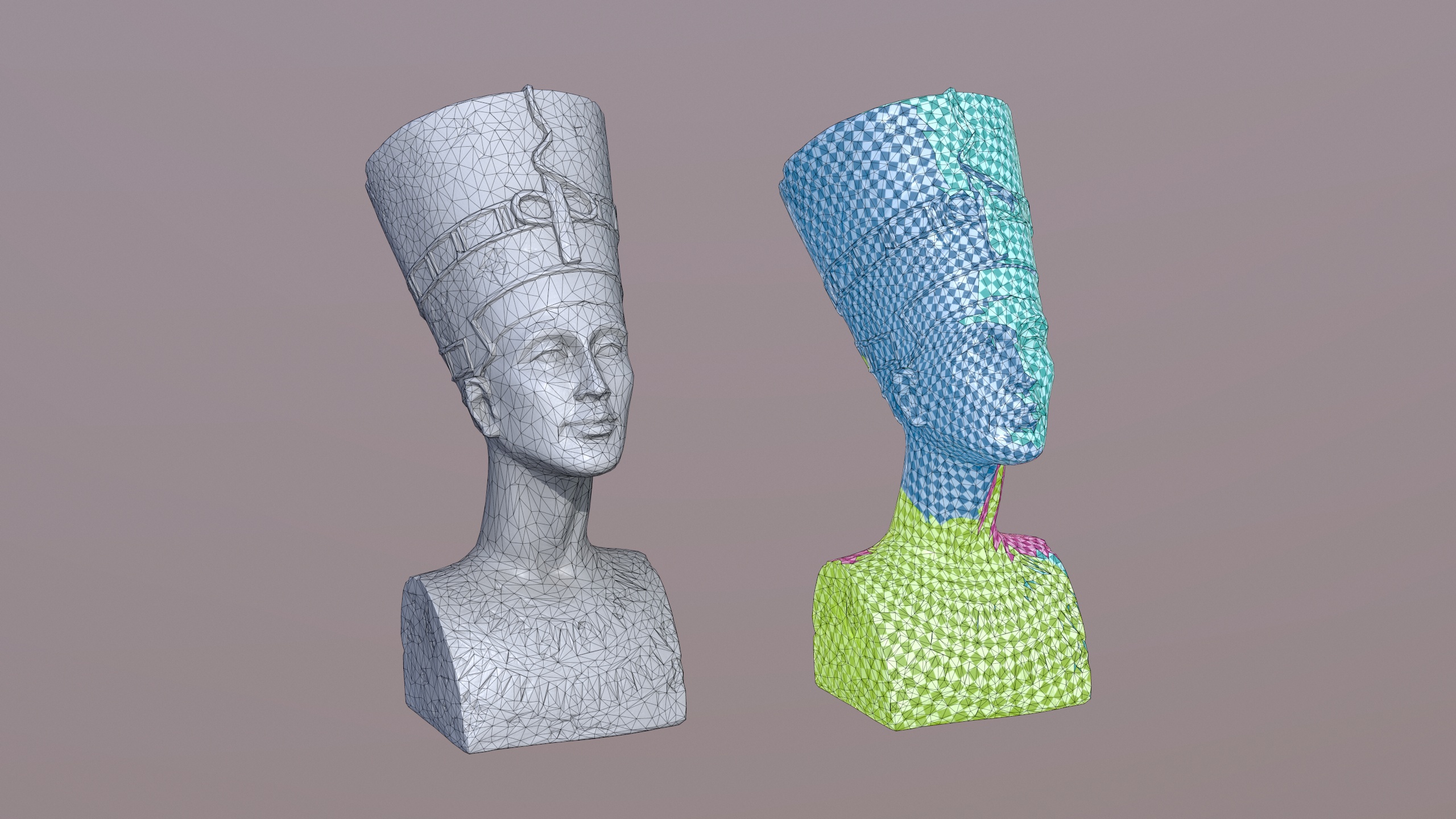
Generating UV Mappings
back to topRapidCompact CLI is a powerful tool for texture mapping, exposing several features of the RapidCompact Library. The UV mapping process typically involves several steps, and can mainly be divided into the following three stages:
- Segmentation
- Unwrapping
- Atlas Packing
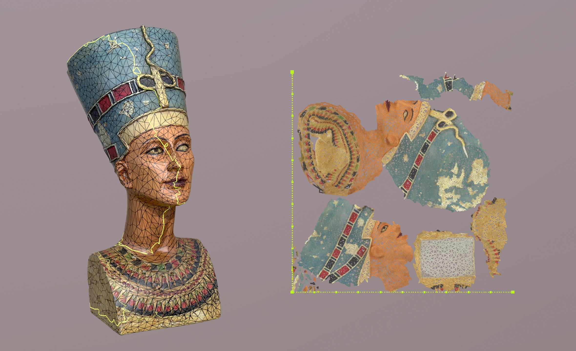
During segmentation, the 3D mesh geometry will be divided into charts that fulfill certain criteria (such as having disc topology). This step might be necessary, since not every mesh can be directly unwrapped by all kinds of parameterization algorithms. Each chart can then be unwrapped separately. During this step, the actual generation of 2D UV coordinates takes place. Finally, the third step arranges one or multiple charts in a (usually square) 2D domain, which is called a Texture Atlas.
RapidCompact CLI does not provide explicit commands for atlas packing. Instead, the atlas
packing step is part of the unwrap command. This is motivated by the
fact that an unwrapping of multiple charts without atlas packing, leading to overlaps
inside the UV space, is usually not usable for very most applications, and may lead
to unexpected results in many cases. Within the following, the
unwrapping command and related settings (including such for texture packing) are
illustrated.
Computing UV coordinates for a 3D mesh is for sure one of the most crucial steps
within a texture mapping pipeline. RapidCompact CLI
offers a fast, high-quality unwrapping which is by default configured preventing
the occurance of any overlaps. The respective command
(--unwrap) is further explained within the following.
| Command: | unwrap |
| Example: | rpdx -i myMesh.ply -u -e
myMesh-UV.obj |
| Description: | Computes a UV mapping for a segmented mesh (or for a single mesh with disc topology). Charts are first unwrapped and then packed into a texture atlas. |
The values of the following settings influence the result of the unwrap command:
| Setting Name: | unwrapping:method |
| Setting Type: | String |
| Valid Values: | conformal, fastConformal, isometric, forwardBijective, fixedBoundary |
| Default Value: | fastConformal |
| Description: |
Specifies the method to be used for UV unwrapping. The different methods
are:
|
| Setting Name: | packing:chartPadding |
| Setting Type: | Real |
| Valid Range: | [0, 1) |
| Default Value: | ~0.0005 (1.0/2048) |
| Description: | Specifies the amount of padding to be used around each chart within the UV atlas. The value is interpreted relative to the unit range of the atlas. This means that, for example, a value of 1/1000 will produce a padding of one thousandth of the atlas' size around each chart. If the constraint cannot be fulfilled (for example, because there are too many charts), it will be relaxed accordingly. |
Generating Color Information and Textures
back to topThe following commands can be used to create vertex colors or texture maps:
| Command: | colorize_vertex_ao |
| Example: | rpdx -i myMesh.ply --colorize_vertex_ao
-e myMesh-ao.ply |
| Description: | Computes computed AO (Ambient Occlusion) at each vertex and colors the vertices accordingly. |
| Setting Name: | ao:vertexSamples |
| Setting Type: | Integer Number |
| Valid Range: | [1, 1024] |
| Default Value: | 100 |
| Description: | Specifies the number of samples taken for each vertex when generating ambient occlusion values. Larger values result in more precise occlusion computation, at the cost of longer computation times. |
| Command: | set_checker_texture |
| Example: | rpdx -i mesh-UVs.obj
--set_checker_texture -e mesh-checker.obj |
| Description: | Attaches a checkerboard texture to the 3D asset. This is primarily useful to visualize the properties (stretch, scale and direction) of a UV mapping. |
The following bake_maps command can be used to create texture maps
for a low-resolution mesh, in order to visualize it with detailed surface properties
from a corresponding high-resolution variant (such as normals, stored in a normal
map). The process of creating such textures is also referred to as
baking.
| Command: | bake_maps |
| Example: | rpdx -i highpoly.obj -i lowpoly-UV.obj
-b -w outWeb |
| Description: | Transfers attributes of a source asset into texture maps of destination mesh, using the UV mapping of the destination asset. The second highest asset of the stack acts as source asset, the topmost asset of the stack acts as destination asset. Usually, a normal map and a base color / albedo map are created. If the destination asset does not have color information (such as vertex colors or textures), it is possible to create the base color / albedo texture using ambient occlusion, computed on the source asset. |
Apart from the baking:baseColorMapResolution setting and similar settings
for resolutions of the other maps, the following settings influence the result of the
bake_maps command:
| Setting Name: | inpainting:radius |
| Setting Type: | Integer |
| Valid Values: | [0, 32] |
| Default Value: | 32 |
| Description: | Specifies the radius, in pixels, to be used for texture inpainting around each chart. |
| Setting Name: | ao:enabled |
| Setting Type: | Flag |
| Valid Values: | true, false |
| Default Value: | false |
| Description: | Specifies if generation of AO texture maps is enabled. |
| Setting Name: | ao:replaceMissingAlbedo |
| Setting Type: | Flag |
| Valid Values: | true, false |
| Default Value: | true |
| Description: | Specifies if AO should be used to replace a missing albedo / base color texture, in case no such texture is available on the source asset during baking. If this flag is switched off, AO will always be written to a separate, dedicated texture map. |
| Setting Name: | ao:textureSamples |
| Setting Type: | Integer Number |
| Valid Range: | [1, 64] |
| Default Value: | 8 |
| Description: | Specifies the number of samples taken for each texel when generating an ambient occlusion texture. Larger values result in more precise occlusion computation, at the cost of longer computation times. |
| Setting Name: | ao:filterRadius |
| Setting Type: | Real |
| Valid Range: | [0, 16] |
| Default Value: | 5.0 |
| Description: | Specifies the filter radius used for smoothing the ambient occlusion texture (if any). Set the filter radius to 0 to disable smoothing. |
Generating Images
back to topSince it can easily be installed on servers an does not require a GPU, RapidCompact CLI can also be conveniently used to generate images of 3D models. This is useful, for example, when you have a large set of meshes and want to create thumbnail images. You can also use RC to render a turntable-like image series, rotating around the up-axis of a given mesh. Such an image series can then be used to display a pseudo-3D view of a 3D model (for example, inside a Web page). Image generation (or rendering) commands share the following common settings:
| Setting Name: | rendering:imageWidth (similar: rendering:imageHeight) |
| Setting Type: | Integer Number |
| Valid Range: | [1, 8192] |
| Default Value: | 1024 |
| Description: | Specifies the width (similar: height) for rendered images. |
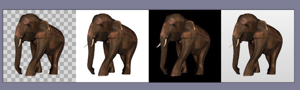
| Setting Name: | rendering:background |
| Setting Type: | String |
| Valid Values: | transparent, white, black, gradientGray |
| Default Value: | transparent |
| Description: | Specifies the background to be used when rendering images. |
| Setting Name: | rendering:showBackFaces |
| Setting Type: | Flag |
| Valid Values: | true, false |
| Default Value: | false |
| Description: | Specifies whether faces with a surface normal pointing away from the viewer ("backfaces") should be rendered. |
If a model should be rendered using a certain camera position and orientation, the
following command set_view_matrix can be used:
| Command: | set_view_matrix |
| Shorthand: | v |
| Argument: | matrix in format "m00 m01 m02 m03 m10 m11 m12 m13 m20 m21 m22 m23" |
| Example: | rpdx -i foo.obj -v "1 0 0 0 0 1 0 0 0 0 1
-1000" --render_image foo.png |
| Description: | Sets the view matrix, used for rendering, to the given matrix. The 3x4 matrix in row major format must be specified as a single, whitespace-separated string, wrapped in quotes. |
If no view matrix is explicitly set, the model is rendered with the camera fitting to the scene, looking along the negative z-axis (if the system was not rotated). The commands for generating images are shown in the following.
| Command: | render_image |
| Shorthand: | none |
| Argument: | filename of the resulting image file |
| Example: | rpdx -i myMesh.ply --render_image
mesh.png |
| Description: | Renders an image of a mesh and stores it to the given image file. Supported image formats are PNG and JPEG. |
| Command: | render_turntable |
| Argument 1: | directory for images |
| Argument 2: | number of views / images to render |
| Example: | rpdx -i foo.obj --render_turntable meshTT
32 |
| Description: | Renders a turntable-like image series by centering the asset and rotating the view around the up-axis. The resulting images will be stored in PNG format. |