Within this tutorial, we are going to use RapidCompact CLI to simplify a 3D mesh. This process is sometimes also referred to as Mesh Reduction or as Mesh Decimation. The latter term, decimation, is used within the RapidCompact CLI options and settings.
RapidCompact CLI has several settings that can be used to control the decimation process:
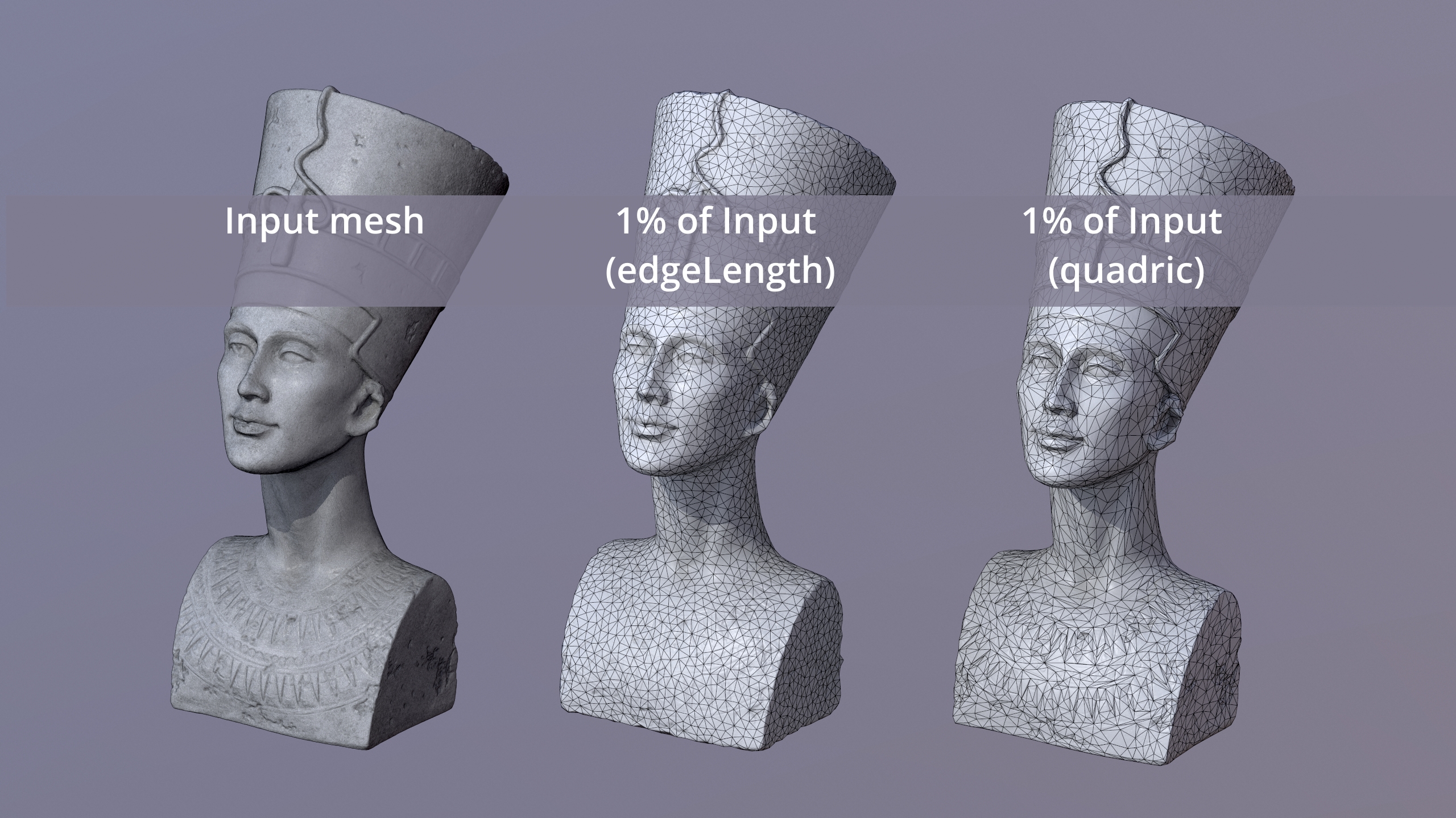
To get started with the decimation functionality of RapidCompact CLI, we will use a simple example mesh of a scanned nefertiti bust, which you can download here.
This mesh has 1,5 million faces, which makes it a medium-sized data set. Although it could already be used like this for many visualization applications, some might require a variant that consists of less triangles, for example for quick rendering in a VR or game context. Another reason for generating a simplified version might be the reduction of bandwidth which is needed to transmit this mesh over a network (for example, for online presentation). Within the following tutorial, we will see how to generate different texture maps, applied on the low-resolution asset, can help us to faithfully preserve the details of the high-resolution original. However, within this tutorial, we will just simplify the 3D geometry of the mesh.
To generate a simplified version of the nefertiti mesh, you can use the following command line:
rpdx -i nefertiti.ply -d 2000 -e nefertiti-lowpoly.ply
This command will generate an OBJ file entitled nefertiti-lowpoly.ply, containing the simplified version of the input mesh. The decimate command, here abbreviated using the shorthand version d, accepts several parameters. By default, a number is interpreted as a target amount of vertices. However, you can also specify a target amount of faces, or a target percentage of vertices or faces. Examples:
The method used by default is the quadric method. There is also another one, which is entitled edgeLength. The edgeLength method is more simple and hence slightly faster, and it produces a resulting mesh where the triangles have a very regular distribution, which can be beneficial for some applications. However, the quadric method will be preferred in most cases, as it preserves features relatively well. The following figure shows a comparison of the results, using a strong simplification to 1% of the original vertices:
A common artifact arising during simplification is deformation of open mesh boundaries. To experience this by example, we will use this model of a teapot.
To see what happens when a mesh is simplified without special constraints for the boundaries, set decimation:boundaryPreservationFactor to zero and run this command:
rpdx -i teapot.obj -d v:500 -e reduced.obj
This will produce a reduced teapot that looks like this:
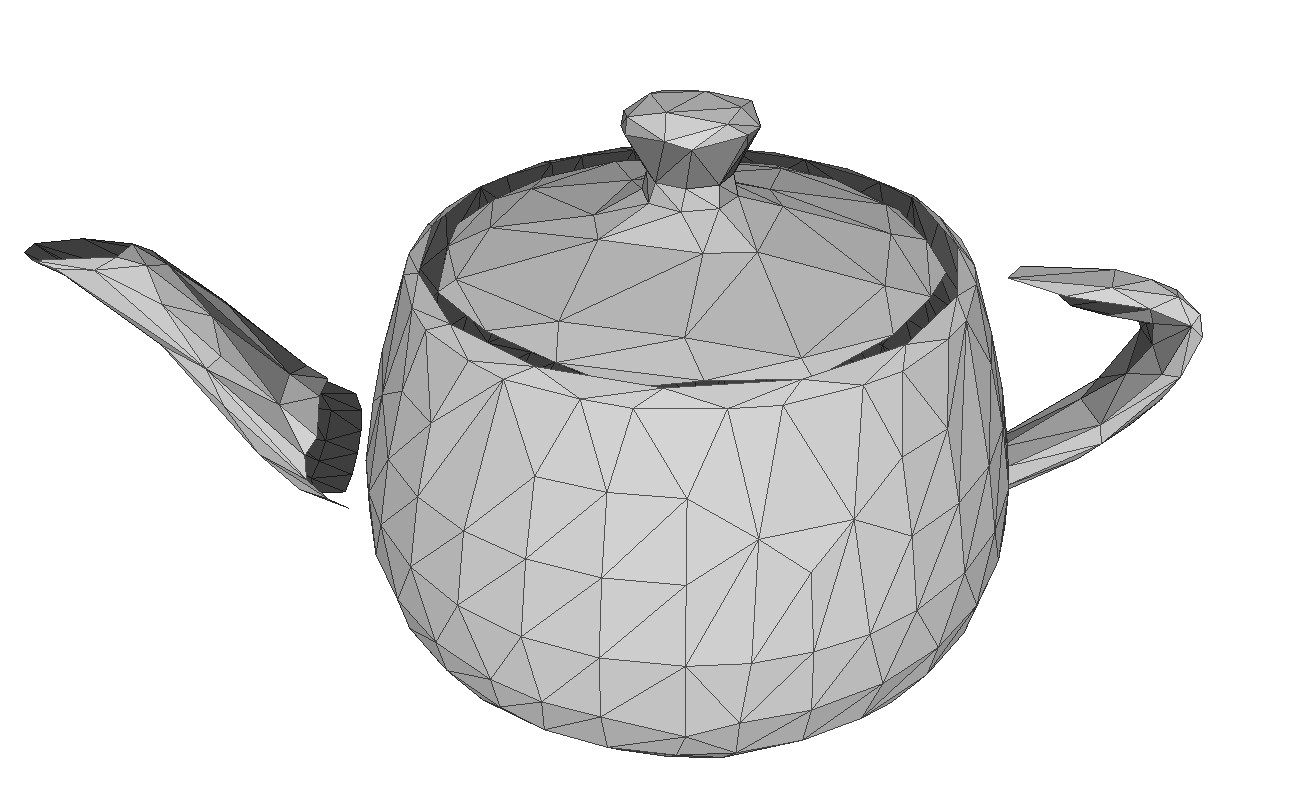
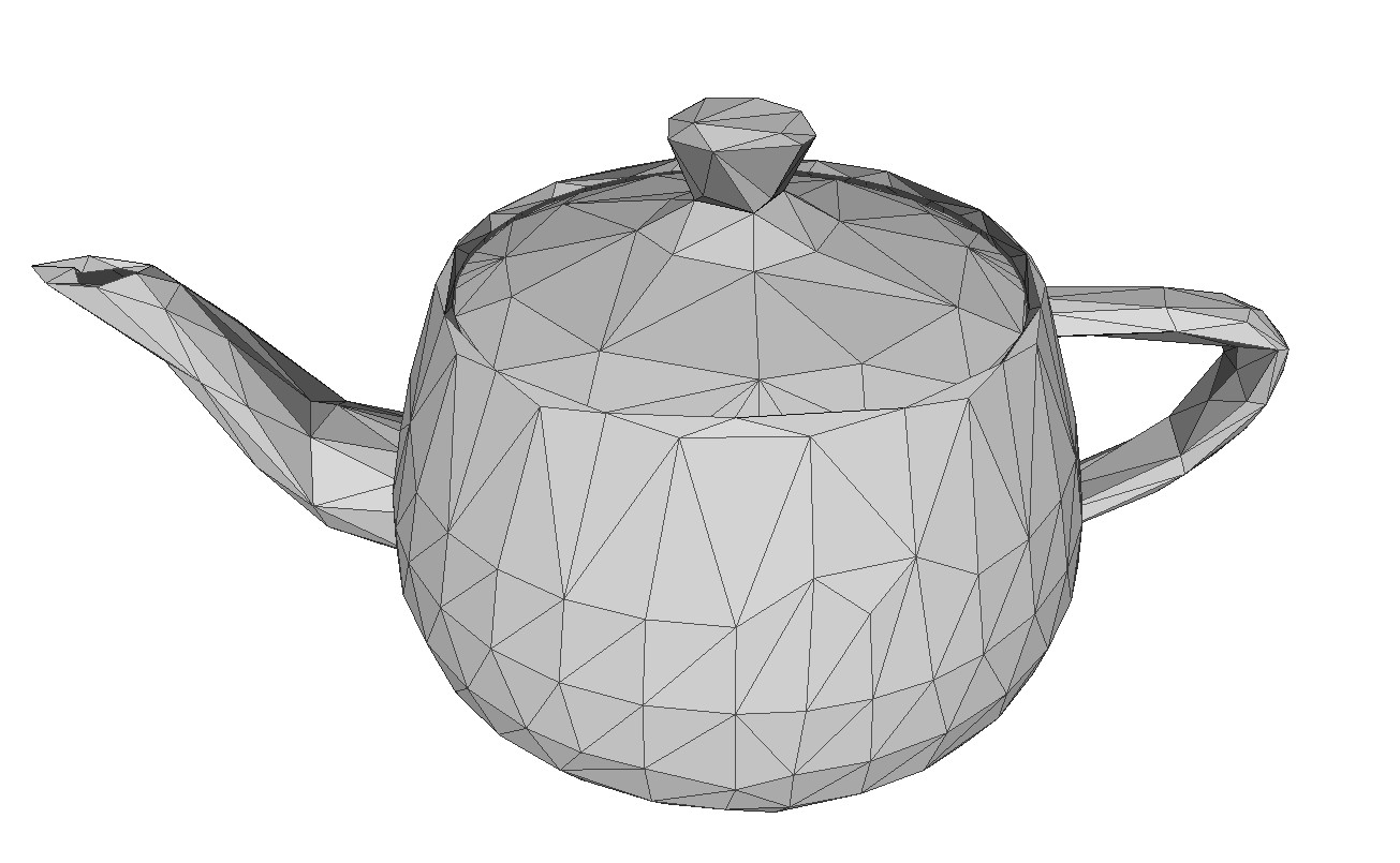
Not very satisfying, you would probably say. What looks especially ugly and "wrong" are the displaced boundary vertices, leading to the handle and spout floating somewhere in the air, instead of being connected to the body of the teapot. The reason for this is that the teapot's spout and handle were actually separate pieces that are not connected to the body's vertices within the original model. In such cases, it helps to apply some special constraints for the mesh boundaries. Setting decimation:boundaryPreservationFactor to 0.5 gives a much nicer result:
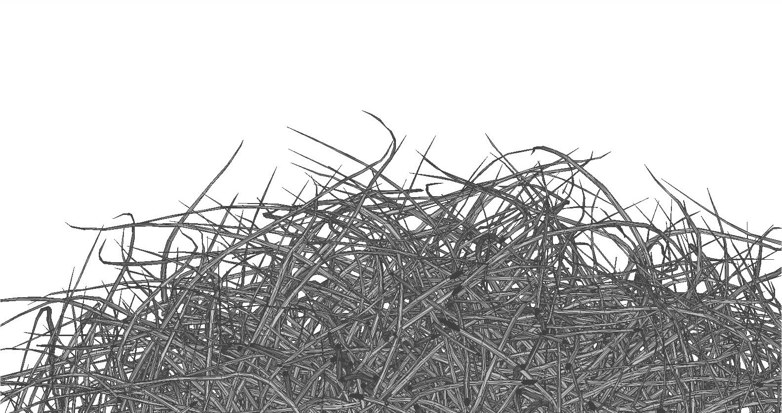
For most visualization applications, we obtain good result by decimating input meshes without caring about the topology of the result. This allows the simplification algorithm to remove small holes or handles, for example, when creating a low-poly approximation of the input mesh. However, for certain applications and certain input models, we may want to preserve the exact topology of the input, meaning: holes should never be closed, and handles and different surface parts should never be merged. Regarding the visual quality of the output, topology preservation can especially be useful when dealing with geometric details like fine strands. Here's an example mesh which we can use for a small test (original Hairball model courtesy of NVIDIA research): hairball.ply A detail view on it looks like the following:
We can simplify this input model to 25% of its faces, using the following command:
rpdx -i hairball.ply -d f:25% -e result.ply
The result will look like the following:
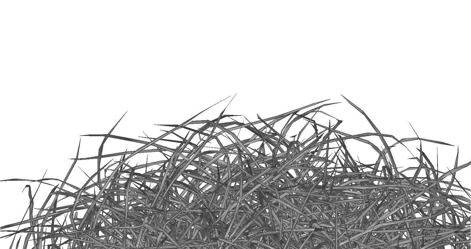
As can be seen, the simplification took away some of the tips of the strands. It also allows, in principle, that the vertices of separate strands will get merged together, or that strands will get split up into multiple pieces possibly floating in the air, in other words: it allows for changes of the mesh topology. RapidCompact can be configured to forbid such changes, using the flag decimation:preserveTopology:
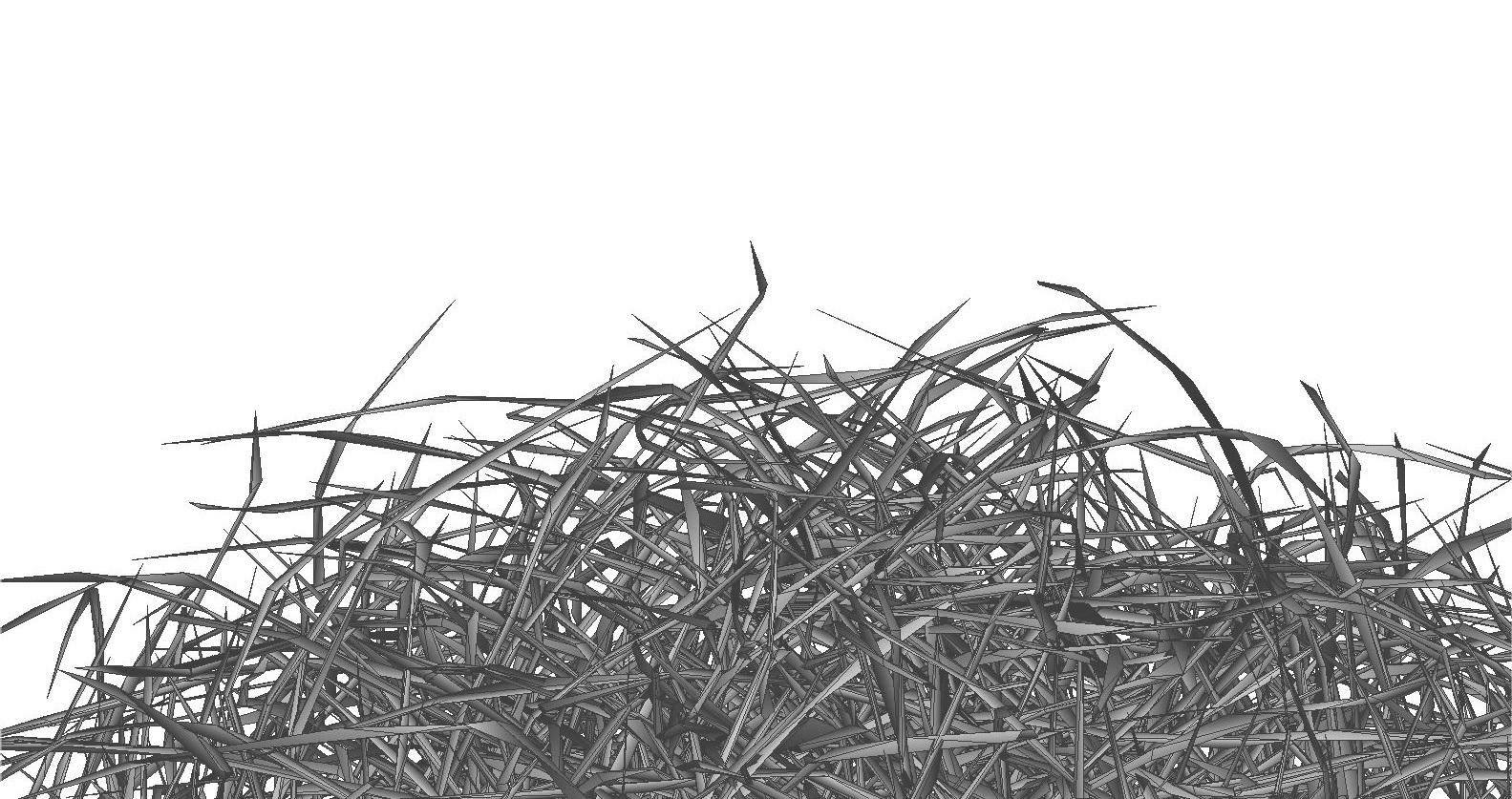
rpdx -i hairball.ply -s decimation:preserveTopology true f:25% -e result-pt.ply
In this case, this will lead to a much better preservation of the many single strands of the hairball, and to a better preservation of its "volume", as no strands will be merged or torn apart by the simplification:
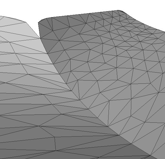
For certain meshes, especially those generated through CAD, the surface may be composed out of several parts, or patches. Such patches are often not explicitly connected at their boundaries, but instead vertex positions of two neighboring patch boundaries will simply match. Without boundary preservation, we might run into problems here, as those boundaries may "crack up" (compare the example of the teapot shown above). In such cases, we can also handle the problem differently: instead of preserving boundaries (using decimation:boundaryPreservationFactor), we can also weld them together. This effectively means that we are allowing the simplification method to merge nearby vertices, regardless of whether they belong to the same surface patch or not. This can be done using the setting decimation:collapseDistanceThreshold, which is a value relative to the model's bounding box diagonal. For this simple example mesh of two bent sheets, setting decimation:collapseDistanceThreshold to zero and performing decimation to 500 vertices will produce a result like this at the boundaries between both patches:
In constrast, by setting decimation:collapseDistanceThreshold to 0.1, we obtain a result where the boundary vertices of both sheets have been "welded" together: